|
 |
|
TECHNOLOGY | Rapid
Prototyping |
|
|
|
| RP - Rapid Prototyping |
| The main section for Rapid Prototyping Technologies and R&D - Research & Development |
| |
Legend |
The principal page for Rapid Prototyping, origin of Rapid Tooling, Rapid Manufacturing technologies, is a complete technologies presentation. Within fantastics video, links to main technologies manufacturers, stations, samples & technologies from plastics to metal, laser, and on next page a complete repertory, it accomplishes a guide for industry, engineering, research & development.
|
 Links to Section or WEB Sites Links to Section or WEB Sites |
 Video Links Video Links |
 Link Portal Pages - Sections Link Portal Pages - Sections |
 Link inside page Link inside page |
|
_RP RAPID
PROTOTYPING_
Introduction
Rapid
prototyping, is the automatic construction of physical
objects using solid freeform fabrication. The first techniques
for rapid prototyping became available in the 1980s and
were used to produce models and prototype parts. Today,
they are used for a much wider range of applications and
are even used to manufacture production quality parts in
relatively small numbers. Some sculptors use the technology
to produce complex shapes for fine art exhibitions.
In brief, rapid prototyping
takes virtual designs (from computer aided design (CAD)
or from animation modeling
software, transforms them into cross sections, still
virtual, and then create each cross section in physical
space, one after the next until the model is finished.
It is a WYSIWYG process where the virtual model and the
physical model correspond almost identically.
In additive fabrication, the machine reads in data from
a CAD drawing, and lays down successive layers of liquid
or powdered material, and in this way builds up the model
from a long series of cross sections. These layers which
correspond to the virtual cross section from the CAD
model are glued together or fused (often using a laser)
automatically to create the final shape. The primary
advantage to additive construction is its ability to
create almost any geometry (excluding trapped negative
volumes).
The standard interface between CAD software and rapid
prototyping machines is the STL file format. |
The
word "rapid" is relative: construction
of a model with contemporary machines typically takes
3 to 72 hours, depending on machine type and model size.
Used in micro technologies "rapid" is
correct, the products made are ready very fast
and the machines
can build the parts in parallel.
Advances in technology allow the machine to use multiple
materials in the construction of objects. This is important
because it can use one material with a high melting point
for the finished product, and another material with a
low melting point as filler, to separate individual moving
parts within the model. After the model is completed,
it is heated to the point where the undesired material
melts away, and what is left is a functional plastic
machine. Although traditional injection molding is still
cheaper for manufacturing plastic products, soon rapid
prototyping may be used to produce finished goods in
a single step.
Due to the high degree of flexibility and adaptability
required by many rapid prototyping techniques, these
applications typically require the use of robots or similar
mechanisms.
However, there are currently
several schemes to improve rapid prototype technology
to the stage where a prototyper
can manufacture its own component parts (see RepRap Project).
The idea behind this is that a new machine could be assembled
relatively cheaply from raw materials by the owner of
an existing one. Such crude 'self-replication' techniques
could considerably reduce the cost of prototyping machines
in the future, and hence any objects they are capable
of manufacturing.
Wikipedia - Rapid Prototypling |
Rapid
Prototyping is to all intents and purposes the the
most common name given to a compound of related
technologies that are used to manufacture physical
objects directly from data sources of CAD. These
methods are only in processes, they add and they
unite materials in layers to form objects.
Such systems are also known by the names: addictive
production, three-dimensional impression, production
of solid free form (SFF - Solid freeform) and production
in layers (layered manufacturing). The addictive
technologies now offer advantages in a lot of applications
compared to methods of production classic subtractive
as machining or lathing:
¤ Objects can be formed with any geometric complexity
without the need of having elaborated adjustments
of machines or final assembly;
¤ Systems of rapid prototyping reduce the
construction of complex objects to a manageable
process,
direct, and relatively rapid.
This resulted in the large employment by engineers
as a way to reduce time of manufacture,
better to specify and to communicate the product
design, and
to produce rapid tooling to manufacture
those products.
|
 |
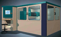
| LabGraph© |
| Images Representing Software transforming CAD models in stl files |
| Training by Virtual Reality - LabGraph© |
|
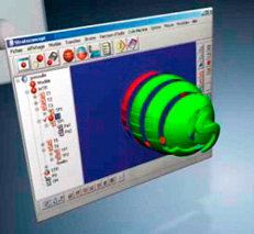 |
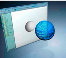
| LabGraph© |
| Images representing stratification by software for standard layers modeling. |
| LabGraph© files Images de Arquivo - Training by Virtual Reality - Simulation |
|
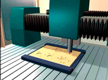 |
Virtual image of CNC ultra-rapid
Milling |
| LabGraph© virtual simulation files |
|
Rapid
prototyping and small series manufacturing (RP&M)
technologies are new technologies to produce one
or more
pieces of solid part from 3D modeling or CAD
software data
promptly, independent of the shape complexity.
Different RP technologies have their advantages and disadvantages. Inside Factory
of Factories program the general function of prototyping will be described
in the product development process, which different activities influence
the choose of RP technologies, and comparing the difference of every RP
technologies.
This reports focus on the field of product design and development, including
rapid prototyping techniques that can be applied to a wide variety of fields,
which the most important is manufacturing individual equipments, vehicles
or devices.
Rapid
Prototyping is not a solution to all problems
of production of pieces or parts:
It
should be observed that the technology CNC is economical,
widely understood and available, offers
wide material selection and excellent precision.
However, whatever the demand involves producing a
part or same object geometry moderately complex,
and rapid execution – RP usually has enormous
advantages.
|
Examining
extreme cases and determining which of technologies
to apply, CNC or RP is relatively
simple. For many other less extreme cases the line
of crossing selection is hazier, it changes the
whole time, and it depends on several pondered
weights,
factors case-dependent. Even whether the precision
of rapid prototyping is not usually perfect as
CNC, it is still adapted for an extensive range
of applications
and precisions requirements.
Introduction
Various engineering techniques are employed in Rapid Prototyping including
CNN Milling, Stereolithography, laser, printing, optical scanning,
resin material development, polymer material extrusion and deposition,
powder metallurgy, sintering processes, etc.
Rapid
prototypes are normally applied for design development
or certification, product evaluation, production & process
analysis, and manufacture tooling fabrication, resulting significant time
saving in product development
and enhancing competitive edge of the company. |
There are approximately
40 manufacturers all over the world making RP equipment
that can be classified into 10 main technology categories (click on subject to see the article):
 CNC Milling Technologies CNC Milling Technologies
Fused Deposition Modeling (FDM)
Inkjet Deposition Methods
Laminated Object Modeling (LOM)
Laser Powder Forming Technologies
Selective Laser Sintering (SLS)
Solid Ground Curing (SGC)
StereoLithography (SL or SLA)
Photopolymer based methods (other than stereolithography)
Three Dimensional Printing (3DP) and related technologies
|
|
The range and available properties
are growing rapidly. Numerous plastics, ceramic, metals
that vary from stainless steel to titanium, and paper
wood-type are available. Anyway, numerous secondary
processes are available to convert patterns done in
a rapid prototyping process into final materials or
mould tools.
Geometric freedom - Essentially all the addictive
production technologies (addition of materials)
provide the ability
for production with limitless geometric freedom.
It is the most important advantage over the subtractive
methods and main reason of their existence. Geometric
freedom still understands several limitations of
the
current technologies.
|
CNC RP milling machines commanded by special CAM software
allows producing Rapid Prototype to Rapid tooling.
CNC
Milling Technologies - CNC RP milling machines
commanded
by special CAM software allows producing
Rapid Prototype to Rapid tooling. Computer Numerical
Control (CNC) in some aspects is related to a
tool or model manufacturing, in which a cutting
machine
such as a lathe or milling machine is controlled
by computer to cut a specified shape, often with
many different steps and cutting tool changes.
The fabrication process builds the part systematically
by cutting material, with a high precision and
finishing.
CNC cutting
and milling has been in use for a longer period
than RP and are relatively common
in manufacturing.
Driven by CAD data there are ranges of applications
for cutting, hole punching, milling, engraving,
etc. and a number of different technologies,
which are used. The best advantages of CNC
are its accuracy
and speed.
The accuracy
of CNC cutting means that elements can fit high
precision and apart from cutting,
CNC can be used for milling, drilling, tapping,
bending, welding, grinding, etc and many
industrial items are fabricated or assembled
from components
at the end of a CNC process.
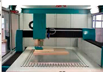 |
Charlyrobot CNC Station ultra-rapid
milling soft materials. |
 |
 Charlyrobot Site Charlyrobot Site |
|
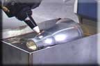
Laser machining
represents a revolution. Before being limited
to profiling work where depth of cut was unimportant,
depth can
now be controlled opening many new opportunities
both in the production of components and in tool
making. The laser can machine virtually any material
and
once
calibrated, establishing possibilities with ceramics
and other previously impossible to machine materials.
Presenting the "tool" diameter of 0.1mm
or less, the laser can attain restrict areas
and create
detail that milling could never reach.
As the "tool" does not wear, providing
always-optimal cutting performance even pre-hardened
steel or tungsten
carbide, is vaporised as the laser traverses
the surface. Similar to many RP systems working
in
layers, except
that the layers are down to one micron thick,
a cavity or section is created by material
removal.
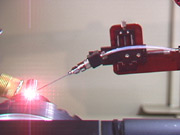 |
TetraPORT SYstems Metal deposition with wire feeder
See Video |
 |
| 5 Axis Laser Video |
 |
| Alabama Laser offers specialized laser research and development services |
|
The FDM technology
involves heating a filament of thermoplastic
polymer unwound from
a coil and provides material to an extrusion
nozzle. The heated nozzle melts the plastic and
flow the melted plastic to be twisted on and
off. The nozzle is mounted into a mechanical
device, which can be controlled in both horizontal
and vertical directions by a computer CAD data
file.
The system is sheltered
within a compartment, which is held at a temperature
just below the
plastic melting point. Each layer is formed
of extruded plastic deposed by the nozzle moving
over the table in the required geometry.
The
plastic consolidate instantly after being
sprayed from the nozzle and attach to the previous
layer.
The machines range from fast concept modellers
to slower, high-precision machines.
The materials
include polyester, polycarbonate, ABS,
elastomers, and investment casting wax.
 |
| FDM™ Vantage |
 |
| Stratasys site link |
|
Metal Spray tooling and electroplating
can be used for parts that are to be constructed using
plastic
production processes, being important resource in
Rapid Tooling.
This process applies a zinc/aluminium alloy
with an arc spray to a pattern or model.
The pattern or
model
can be a stereolithography part or a model
made from wood, composite, plastic
or metal. The alloy is sprayed
over the pattern to a shell thickness from
.060-inches to 0.125-inches as required.
As soon ass it hardens
into the desired shape and adheres to the
pattern, the sprayed metal shell is
then reinforced with high-treat
aluminium-filled epoxy resin or caster
aluminium or low melt metal alloy.
The finished mould can produce parts from
virtually any production material, from
polypropylene to glass-filled
polycarbonate. The longevity of the tool
is process dependent. Low-pressure operations
such as casting,
blow moulding or rim will yield more
parts than the higher pressure applications.
Turnaround time for
producing a sprayed tool from Rapid Prototype
Pattern is between
ten days to three weeks depending on
complexity
of the tool.
Types and Quantities of Parts Made:
· Polyurethane 300 to 20,000
· Polyurea 300 to 20,000
· Epoxy 100 to 600
· Investment Wax Patterns 500 to 10,000
· Low Melt Metal Alloys 100 to 1,500
· Polyurethane Foam 2,000 to 20,000
· Silicone Rubber 10,000+
· Injection Moulding 10 to 1,000
· Rim Moulding 1,000 to 15,000
· Blow Moulding 300 to 500
· Vacuum Forming 5,000 to 100,000
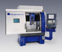 |
| TRULASER 3010 - link |
 |
| Site Trumpf - link |
|
Inkjet Deposition methods utilize a single jet each
for a plastic fabricate material and a type of wax
as support
material, which are held in a melted liquid state in
containers.
Jetting heads moving in the
axis spray tiny droplets of the materials in the required
pattern
to
form a object layers. The materials solidify rapidly
as they are deposited.
 |
| Digimatix DMP-2800 |
 |
| Digimatix FujiFilm Site link |
Using a photopolymer process
based the system uses a wide area inkjet head to layer
judicious deposit
building
both model and support materials.
After each layer
a UV flood lamp mounted on the print head subsequently
completely support and model material. The support
material
are removed by washing it away with pressurized
water in a consequent operation.
|
|
Applying
a laser to cut the profiles of the model
cross-section on paper, plastics, and meshed
or metallic
material the system accomplishes a low
cost process.
Laminated
object manufacturing (LOM) is a rapid prototyping
process where
a part is built sequentially from layers
of paper. A feed roll supplies a tape
bonded to the previous
layer melting a plastic coating to the
bottom side of the paper.Successive
layers of heat bonded sheet material form
the model using typically
paper. A laser system controlled by a sliced
CAD data is used to cuts the perimeter
of each slice in the sheet material. A
heated roller will apply the next sheet
layer, and waste material around the slice
is left in place to support the next layer
of the model.
Applying
a laser to cut the profiles of the model
cross-section on paper, plastics, and
meshed or metallic material the system accomplishes
a low cost process. A feed roll supplies
a tape bonded to the previous layer melting
a
plastic coating to the bottom side of the
paper.
One of the most important problems of LOM
is the process of hot pressing. The purpose
of
hot pressing is binding the current layer
to the built part. The speed of hot pressing
must
match with the power of heating up. If the
of hot-pressing movement is too fast, the
binding between layers the layer will not
be rigid;
while if the movement is too slow, the layer
will be over-heated and the hot stress of
will affect the shape of object. Another
question
is focused onto attain the cutting speed
and the power of laser beam.
The
LOM process is very advantageous in many
aspects. First, because the laser beam
only cut the outline of shape, this process
can
decrease process times than other RP. It
is the most efficient process in all kinds
of
RP process. Secondly, the LOM process can
manufacture very complicated object. The
complicacy of
the LOM object is less limited than the
FDM (Fused Deposition Modelling) object
because
there is no need of support material in
the LOM process; low material cost is also
an
advantage of this process.
The
system has a low cost, and even ceramic
and composites were used for the
process, but accuracy and stability
are not outstanding.
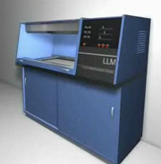 |
| LOM (LLM) click to see video from the site RTe |
 |
RT ejournal
Forum for Rapid Technologies |
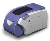 |
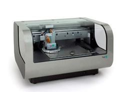
| CUBIC SD300 |
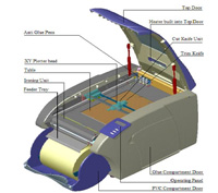 |
| CUBIC SD300 parts |
 |
| Cubic Technologies Site link |
|
Laser powder molding technologies are obtaining
large importance and are a promising technology.
Using
a high power laser to melt metal powder feed coaxially
to the focus of the laser beam by a deposition
head, the laser beam typically moves through the
center
of the head and is focused to a small spot by the
lenses.
The table X-Y moves
in raster method to fabricate each layer of the model
as the head moves
up vertically
to complete each layer.
|
Developed
by the MIT institute the process comprises
depositing a layer of compressed powder material
at the top of a fabrication chamber and a
multi-channel head jet subsequently a liquid
adhesive in two dimensional patterns that
will bond the powder where the liquid is
deposed following the shape, and forming
each layer of the model.
3D
printing is an innovative process, which uses
a multi jet modelling head to apply
a thermo polymer material in three dimensions.
The completed CAD solid model is transferred
to a STL data file, ready for the shape
process. Parts
are produced by the print head consisting
of multiple jets that build the model layer
by layer.
If the
part is larger than the head work space,
the build platform will reposition within the
Y-axis
such
that the process may continue.
The
final model has appearance similar to that
produced with Rapid Technologies such
as Stereolithography, Laminated Object Manufacture
and Laser Sintering,
or meaning a stair stepped appearance.
Duplicating freeform shapes within discrete
layers creates
these
undesirable effects. Constructing models
of thinner layers reduce the stair stepping
effect, but thicker
layers may still be acceptable within
concept modelling.
Most
of the models built using the 3D printer method
are weak and can easily be damaged
and deformed.
In this case infiltrating with wax
can strengthen these models, and adding ink
to
the initially transparent
wax can produce parts that have a variety
of colours.
Support
structures are required to hold temporary the
part before it is finished.
Some types of rapid
prints require post-processing, moreover
for design reliability or aesthetic
appearance. Making the
part more attractive for presentational
purposes the characteristic
post-processing finishing involves
sanding or painting.
 |
| 3D Printing - click to see video righ from the site RTe |
|
RT ejournal
Forum for Rapid Technologies |
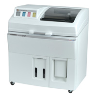 |
| Spectrum Z® 510 |
 |
| Z CORPORATION Site |
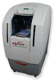 |
| Invision HR 3-D Modeler |
 |
| 3D Systems |
|
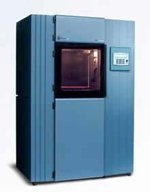
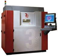 |
| Sinterstation® Pro SLS® Systems |
|
| 3D Systems Site |
|
|
| FDM Vantage |
|
| STRATASYS Site Link |
|
|
The developed rapid casting mould technique significantly reduces the lead-time of mould making and simplifies the process of metal casting.
The process provides the capability to produce cast metal parts from a CAD file considerably faster and less expensively than traditional prototype casting methods. The process involves printing molds and cores on a 3D Printer directly from digital data, eliminating the pattern and core box production step in the traditional sand casting process. Metal is then poured into the 3D printed molds. The technology allows to prototype parts in metal that were previously cost and time prohibitive.
The whole mould building process is implemented automatically by the DMD system without the pattern fabrication step.
It may be possible to produce ceramic casting molds for metal casting using a layered printing process depositing a liquid binder onto a layer of ceramic powder. After the mold is "printed", it is then fired. These molds will handle any metal and are more accurate than those from sand casting. |
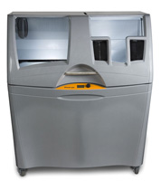 |
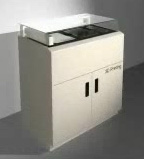
| Z Printer® 450 |
|
| Z CORPORATION Site |
|
|
The system applies a thermostatic powder over
the surface of a cylinder, which moves down
to settle the new
layer of powder to the model. The tightly
compacted powder is melted and bonded by
a controlled laser
beam.
A layer manufacturing
technology in which the layers are formed by
using a laser to bond the surface of a layer
of powder material in the desired shape. Selective
Laser Sintering (SLS) is a free-form fabrication
technology developed by the 3D Systems. It is
a layered manufacturing method that creates solid,
three-dimensional objects by fusing powdered
materials with a CO2 laser. A thin layer of powder
material is laid down and the laser “draws” on
the layer, sintering together the particles hit
by the laser. The layer is then downward by a
layer thickness and a new layer of powder is
placed on top. This process is repeated layer
per layer until the part is complete.
The
advantages of SLS over Stereolithography
(SLA) involve mainly material properties,
as
SLA process is limited to photosensitive resins
that are typically fragile.
A great variety of materials can approximate
the properties of thermoplastics such as polycarbonate,
nylon, or glass-filled nylon are available
for the SLS process. Meanwhile the smoother
surface
of an SLA part typically wins over SLS when
an appearance model is required.
A SLS type machine consists of two powder magazines
on each side of the work area. One roller
moves powder over from one magazine to the
other
magazine crossing over the work area. The
laser then draws
the CAD file out the layer. The work platform
moves down one layer by the specific thickness
and the roller then moves to the opposite
side. The process repeats until the part
is finished.
Normally
the surface of a SLS part is powdery, due
to the base material whose particles
are fused together without complete melting.
|
Stereolithography is a method to build plastic
models or parts using a photopolymer liquid
in a container
where the laser beam will trace the
forms and solidify the liquid bonding to
the previous surface.
Generally provides the highest accuracy and quality
surface of any prototyping technology.
Stereolithography (SLA) is a free form fabrication technology,
the first Rapid Prototyping process, was
developed in 1986. It is a layered manufacturing
method that utilizes a photo-curable liquid
resin in combination with an ultraviolet
laser. A storage bin of photosensitive resin
contains a platform that can moving vertically.
The
construction part under is supported by the
platform that moves downward by a
layer thickness --typically about 0.05
mm to 0.25 inches-- for each layer. When
the
ultraviolet laser beam hits the liquid
it hardens a small amount of resin under
the
beam point A laser beam “draws” the
shape from CAD design of each layer and
solidifies the photosensitive resin.
Stereolithography was developed by 3D Systems.
Due to its accuracy and surface finish, it
has become the most popular of the rapid
prototyping methods.
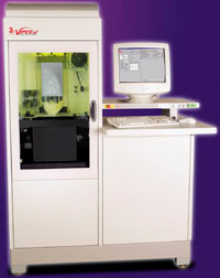 |
| Viper SLA® Systems |
|
| 3D Systems Site |
|
Also
known as the lost wax process is one of the
oldest manufacturing processes. Complexes shapes
can be
made with high accuracy. Hard to machine or
manufacture metals are indicate for this process.
It can be
used to make parts that have complex shapes cannot
be
produced by normal manufacturing techniques,
such as turbine blades, parts that have to
withstand
high temperatures. Using a computer solid model
master a wax pattern is made using a stereolithography
or
similar model prototyping.
Making
a pattern using wax or some other material that
can be melted away, makes the mould. Dipping
a wax pattern in refractory slurry, a skin forms
wrapping the wax pattern. As soon as this is
dried and the process of dipping in the slurry
and drying
is repeated until a robust thickness is attained.
Following the entire pattern is placed in an
oven and the wax is melted away leading to a
mould that
can be filled with the molten metal. Because
the mould is formed around a one-piece pattern,
(which
does not have to be pulled out from the mould
as in a traditional sand casting process, very
intricate
parts and undercuts can be made.
Materials
as Aluminium alloys, Bronzes, tool steels, stainless
steels,
Stellite, Hastelloys, and precious metals can
be cast in the
moulds. Due to close tolerances that can be
achieved
parts made with investment castings often do
not require any further machining.
|
See Next Page RP and RT directories
Complete guide to RP technologies, suppliers, technical & performance
information. |
|
|
| |
|
|
|
|
|
|
|
|