
AUTOMATION & ROBOTICS
Automation may be defined as the set of methods to
achieve automatic control of a manufacturing process
through successive stages without direct human intervention
22. These methods may incorporate aspects of electronic,
mechanical and computer-based technology in order to
operate and control the overall system. It can be classified
into three main classes:
a) Fixed automation, a relatively inflexible system
used for high production volumes where the sequence
of operations is given by the equipment configuration;
b) Programmable automation, where the sequence of operations
can be changed to adapt to product configuration in
smaller batch production jobs thus allowing flexibility
with respect to product changes;
c) Flexible automation that is an extension of the
previous category to incorporate much greater changeover
flexibility and continuous adjustment to a variable
product mix.
|
MODELLING
AUTOMATED
PRODUCTION SYSTEMS
Virtual Manufacturing
and Robotic Cell Design (30)
To meet the pressures of time-to-market, factory
layout and process design software must
be as fast and flexible
as 3D CAD product design packages. Virtual
manufacturing, the digital factory, or
factory simulation software
is a response to this challenge. Current
packages offer a range of tools to handle
automatic assembly sequences,
for instance by capturing data on:
¤ Human motion/accessibility
ranges during assembly tasks,
¤ Potential
collisions for given equipment placement and operations, and
¤ Optimum work
flows for parts of different sizes.
For simple analysis without spatial constraints, 2D
and 3D icon-based products are probably sufficient.
More sophisticated software commercially available
today allow the use of non-standard machines with many
different attributes. Work cell virtual fly-through
and assembly task ergonomics can be incorporated into
the virtual manufacturing picture as well as detailed
robotic control programming or CNC simulation software.
Existing technology allows the simulation of almost
any aspect of product and process design at varying
levels of complexity and success. For instance, human-machine
interactions can be represented through ergonomic models
for training purposes or to evaluate mechanical and
global performances. The former evaluation may make
use of structural simulation, collision detection,
robot controllers or CNC program simulation. These
simulations may use Monte Carlo techniques, continuous
or discrete simulation approaches.
Robot cell design is a particularly difficult task
that requires 3D representations because 2D views may
be misinterpreted. The are several requirements to
meet:
¤ Predict robots
or automates movement,
¤ Avoid interference
between moving equipment or automated devices
¤ Determine
the optimum placement for maximum reach
¤ Design within
confined spaces with high risk of collision
¤ Identify possible
production bottlenecks
|
¤ Minimise the
length of total production cycle.
¤ Consider safety
requirements (including equipment), rules and regulations
¤ Avoid injury
risks
¤ Consider training
needs for operators with no risk for either trainer or trainee.
Faster
work cell layout design (and re-design) tools
can minimise the required engineering design
effort
and reduce down time associated with
on-line programming.
Costly mistakes can be avoided, for
instance by resetting equipment's reach and
collision detection
parameters
to meet scheduling requirements. More
importantly, the optimisation of the work cell
can be evaluated
and programmed off-line, allowing the
system to continue operating during the planning
phase. The resulting
requirements for the supporting 3D
simulating system become obvious (31):
(a)
It must be a powerful and user-friendly
tool
(b)
Accurate models of real industrial must
be easily accessible
as well as mechanical modelling
tools (for example, through
a library)
(c)
Automated tools placement must be represented
to
test reach, tool orientation
and highlight any
changes in cell
configuration
(d)
Other automated plant components
such as conveyor
belts, part feeders,
CNC machines
may also need to
be included in
the simulation
model
(e)
A calibration facility must
be available
to increase
model accuracy (32)
(e)
A collision detection feature must be included
in the software;
integration between production
scheduling routines and the simulation
model is
highly desirable
(g)
Off-line programming facility for subsequent
downloading is
a cost-effective feature
(h)
Simulation, calibration and
off-line programming
of industrial
automated equipment should
be possible,
ideally using
a standard low-cost
desk
or laptop PC.
|
______________________________________________
COMMAND & CONTROL
It
has been argued that the pressure on new developments in the field
of command and control
is largely due to the shortcomings in the automation field (33).
In today's multi-product manufacturing environment, human and material
resources must be managed in a rational and concurrent manner.
The
optimisation of flows throughout the production system is a main
priority as well a dynamic allocation of available material resources
to minimise costs and delays in production and distribution.
The
flexibility requirements impose a dynamic adaptive system that
responds well to internal and external shocks such as equipment
maintenance
requirements and market demand fluctuations, respectively. Industrial
needs require a command and control system that can be easily
responsive to its fluctuating needs in real time while remaining
capable of
evolving and being reconfigured with relative ease. Modular command
and control systems seem particularly adapted to the reactive
and dynamic needs of industry.
The
problem facing command and control system designers is to develop
a multi-agent
architecture with a communication network, which links
the various system agents. These agents may be physical or abstract
with relative levels of autonomy and capacity to affect their environment
as well as change their own behaviour. For that, they dispose of
a partial representation of their environment obtained through embedded
means of perception and communication.
The
resulting behaviour rules observed are a consequence of the agent's
own observations, level
of knowledge and interactions with other agents. If the agent's
knowledge is to be shared with other agents in real or virtual
form and the
amount of redundancy are important design considerations34. In
short, the agents have a social tendency vis-à-vis the entire
system as well as an individual tendency centred around its own
operating
rules. All agents have characteristics such as:
|
a)
Intentions and objectives as the agent moves towards
a pre-defined set of goals given the means available
b) Rationality as an agent will select the best course
of action based upon a set of evaluation criteria
c)
planning ability in that an agent will co-ordinate its
actions with other agents
and
will
plan how to attain its own objectives
d) Adaptability with respect to the environment
and the other agents with which one agent interacts;
e)
intelligence if the
agent has
all the characteristics listed in a) to d)
Complex intelligent agents have an explicit representation of their
environment, may keep track of past performance and events, and are
probably small in number. Most systems also contain a large number
of reactive agents with limited protocol and communication skills
and no explicit representation of the outside world. Not all agents
are required to be individually intelligent for a command and control
system to be considered intelligent. The three objectives of a multi-agent
system can be summarised in three words: communication, control and
organisation 35. There are various design options in terms of communication.
Agents may be unable to communicate directly with each other but
go through a common blackboard. They can exchange asynchronous messages,
be spatially distributed with a large degree of autonomy, and rely
on a set of pre-defined production rules placed on an inference engine or follow recent trends
towards the more abstract holonic or neural communication system.
Command
and control architectures can be classified depending upon the
forms of communication and control used throughout the system.
These may be a meta-object agent, supervisory agents, cell agents,
product agents and finally resource agents, the latter being non-intelligent
in classic workstations 36. The control architecture may be centralised
(with and without pre-planned production schedules), hierarchical,
co-ordinated, distributed and finally distributed and supervised.
In the case of the co-ordinated and distributed architectures, intra-level
communication links exist with or without a global supervisor (37).
|
SUPERVISED
DISTRIBUTED
C&C
ARCHITECTURE
The choice of the most appropriate
command and control architecture depends on several process
design parameters. These include the total number of machines,
required response times, the configuration of the production
system itself (e.g. use of cells, number of identical and
non-identical cells), communication requirements among
machines and/or cells, trade-off between intelligence and
reactivity requirements, and the existence of a production
schedule that can be used for pre-planning purposes.
The
ideal architecture is reactive, robust, fast and reliable (33).
Once it is provided with product type, quantity, delivery
date, optimum starting date and product priority code,
the system must be able to locate the necessary resources
(inputs, machines, etc.) and evaluate their availability
in time and space.
In summary, the command and control function is in a
central position linking Production Planning and Scheduling
and Automation and Robotics. It transmits scheduling
orders and their due dates to the operating equipment
in the production plant after identification of the resources
required for particular tasks. This function requires
translation and interpretation between two different
languages.
What makes this function particularly critical is the
fact that it can evaluate equipment availability. In
the case of malfunctions for instance, it can adopt remedial
measures in real time, one of which may be to demand
an alternative task/resource scheduling routine that
will temporarily eliminate the faulty machine from the
circuit.
The speed of the response time is an important measure
of effectiveness of the command and control function.
Alternatively, the quality of the command and control
function response may be considered an important alternative
to speed. In this case, once faced with a resource availability
problem, the system makes an extended analysis (without
time consideration) and capitalises on that new knowledge.
In that situation, the command and control system is
often based on an expert system and the rules base consists
of acquired working knowledge.
|
Once the best solution
for a particular problem is obtained, it will be reused
in a similar situation. Evidently, these two philosophies
cannot be applied simultaneously to the same type of
systems. The second type in particular is reserved for
systems when response time is irrelevant (as in the case
of long production cycles) but it is imperative to apply
the best remedial solution for a particular problem because
of costs, for instance. As discussed in detail above,
there are three broad choices to automate the command
and control function:
¤ A
unique application manages all, an ideal choice for
small systems because
of the risk of an explosive
increase in operating time for large systems.
¤ A multi-agent
application in which each agent is assigned to a particular task, a much more
flexible alternative.
There are many architectures of this type, the choice
of which depends on the particular configuration
of the operational system.
¤ A multi-expert
system that is a particular application of the multi-agent system where each
agent is an
expert system. This particular choice is almost exclusively
applied to systems adopting the second philosophy
where the quality of the response is more important than response
time.
In conclusion, the command and control module plays
a central role in the CIM chain. It simplifies the shop-floor
manager job by automating some of the managerial functions.
It provides a reliable link between scheduling and numerically
controlled automated machines by translating and interpreting
scheduling requirements. Finally, it relies on a high
performance computer system for quick reactivity to endogenous
and exogenous shocks to the productive system.
|
____________________________________________
PRODUCTION PLANNING,
SCHEDULING AND PLANT LAYOUT
Production planning
41 is typically a medium-term activity. Based on demand
for the various products to be manufactured, production
is allocated to time periods within the planning horizon,
taking into account capacity constraints.
The
plan will depend on the relative values of set-up costs
and of
carrying inventory from one period to another. With
large set-up costs, longer production runs are preferred.
On
the other hand, when set-up costs are small, then short
production runs are chosen in order to avoid the expense
of holding larger inventories. Various complications
arise in production planning models.
Since
the plans are usually designed for several months in
the future,
not all customer orders will have been received.
Thus, forecasting techniques play an important role
in estimating
demand. Also, complex products may require work in
different departments or on different machines. In
such cases,
any precedence rules between different operations
must be respected. Planning decisions are also affected
by the availability of resources such as machine
capacity
as well as constraints on labour or materials.
Production
planning problems operate at a fairly high level
of aggregation,
and do not account for the movement of work between
machines on an hourly or daily basis, for instance.
This level
of analysis is performed by production scheduling
specialists.
|
_________________________________________
PRODUCTION SCHEDULING (42)
Production scheduling is a short-term activity and provides
a detailed specification of the work that the machines
are to perform, usually over the period of a few days
or weeks. In a scheduling problem, jobs must be processed
within the time period fixed at the production planning
stage, as well as their arrival times and due dates,
whereas the order in which the jobs are to be processed
has to be determined.
The most basic model requires a single machine to be
scheduled. If there are several machines performing the
same function, a parallel machine-scheduling problem
results. More complex models require several operations
at different stages to be performed on the jobs. In a
flow shop, every job passes through the machines in the
same order. However, in the more general job shop model,
different jobs have different machine routings and a
job may revisit a machine (in a re-entrant system).
The objective is sometimes to minimise the maximum completion
time or the sum of weighted completion times of the jobs.
However, in the presence of due dates, the objective
may be to minimise other performance measures such as
the maximum lateness, the total weighted tardiness or
the weighted number of late jobs.
With the increased use of flexible and automated machinery,
scheduling problems differ from the classical ones mentioned
above. More precisely, the assumption in classical scheduling
is that each type of operation is performed on a dedicated
machine or group of machines, whereas in modern production
systems, there is often a choice of which machine or
tool to use for an operation. Thus, scheduling problems
require an allocation of operations to machines as well
as the determination of the operations processing order
for each machine.
The investment in the provision of an automated production
system is often substantial. To reap the benefits of
such heavy investment, a high level of utilisation of
the machinery should be achieved. For the repetitive
manufacture of high volume products, therefore, a common
objective is to maximise the throughput of the products.
|
__________________________
PLANT LAYOUT
An important feature in the design of a manufacturing
system is the positioning of machines on the shop floor.
The layout of machines will be constrained by the available
space, and the need to access the machines, either by
operators, by a transportation device to move work between
machines, or for maintenance to be carried out. Ideally,
a layout should position machines close together if there
is a high flow of work between them.
Many layout models consider the problem of assigning
machines to predetermined locations on the shop floor.
If the objective is to minimise the flow of work between
a machine pair multiplied by the distance between these
machines in their chosen locations, summed over all machine
pairs, then the resulting model is a quadratic assignment
problem.
Other models lead to graph-theoretic formulations.
By assigning a weight to each machine pair to indicate
the desirability of locating these machines in adjacent
positions, the problem of maximising the total weight
of adjacent machines becomes a planar sub-graph problem.
More specific layout problems arise when the layout
must conform to particular type. Types of layout include
single row, multiple row and loop, where the single row
can take the form of a linear, U-shape or semicircular
layout. For a linear layout, it is often desirable to
sequence the machines so that
backtracking to previous machines is minimised.
However,
for a loop layout in which the machines are arranged
around a conveyor, it is appropriate to sequence the
machines to reduce the number of loops required to manufacture
the products.
A
particularly important decision concerning
plant layout is the use of manufacturing cells.
In this case, the
manufacturing of a particular part type requires
a sequence of operations to be performed by
any machine of a given
type. The cell formation problem consists in grouping
machines into cells and assigning operations to machines
as to minimise inter-cell traffic, for instance (43).
|
_______________________________________________________
ALTERNATIVE CONFIGURATIONS
FOR THE FMS INDUSTRIAL PLANTS
The application of concurrent engineering principles
during the first drawings meant that the modules
would be given general information about the
case study and that the staff would formulate
their own set of preferences to select the best
design for that FMS.
Given
the wide variety of modelling approaches
used in process
design and the interdisciplinary
nature of most planning groups and in this
project, the choice of a common and easily
understood
modelling tool is a major concern. Graphs,
3D Design & Simulation are selected
as modelling tools for the FMS design analysis
for some reasons:
¤ It
is commonly used in disciplines dealing
with flow optimisation such as
logistics, production
planning and plant lay-out
and a modern standard in automation
and robotics,
or command and
control;
¤ It
allows the joint evaluation of module
solutions;
¤ It
provides a smooth convergence to
a global optimum solution,
if one exists.
For one case study, various design features and
all feasible combinations have to be assigned,
the set of logically consistent options across
modules define the best feasible solution,
if one exists. Each of the modules is based
on experience or modelling results but should
take into account preferences from other modules,
i.e. optimised solutions.
Internal
module preferences may be fully represented
in the
3D simulations techniques (such as the
A&R - Automation and Robotics module) but
be reflected in the total weight placed on a
particular design. In some other cases, the complete
set of individual module objectives cannot be
evaluated in the global context (such as balanced
workload, long production runs and location of
WIP - Working in Process storage for the P&L
- Production & Layout module). In this case,
modules may simply assign a global weight to
the set of design features available before providing
its own contribution (this is the case for the
P&L and the M&L - Maintenance & Logistics
modules shown bellow in the FMS designs). In
some other cases, modules may not assign any
intermediate options.
Although this approach provides several feasible
solutions, it has the disadvantage that the amount
of information increases from top to bottom.
Subsequent runs of the same problem in a different
order may alter the order of preferences and
the ranking of the solutions. The selection of
the most desirable module consultation order
is one of the simulator's decision variables
in its search for optimality.
For example, the C&C Command & Control
module may be consulted at the bottom end rather
than at the top of the tree because it requires
a significant amount of information from other
modules. This includes the number and type
of machines proposed, the use of cells for
production
(or not), scheduling, maintenance and logistics
requirement.
The
M&L
module requirements will have an impact on
plant layout and equipment choice.
And so on. In other words, there is an important
role to be played by the 3D simulator. Otherwise
it must be decided the order in which it visits
the modules, how to obtain global feasibility,
how to impose additional constraints on individual
modules if necessary and finally how to move
towards global optimality.
In a case study, many feasible solutions are
identified, a number of which being clearly superior
to the others thus providing an important first
step to discuss optimisation as well as the best
approach for the general case. The drawings below
are a summary of the strategic decision variables
selected by each of the four modules and the
set of solutions assigned to the various options.
The complete set of options and options for the
case study following the analysis and approval
were simulated to propose a Generic FMS design.
|
____________________________________________
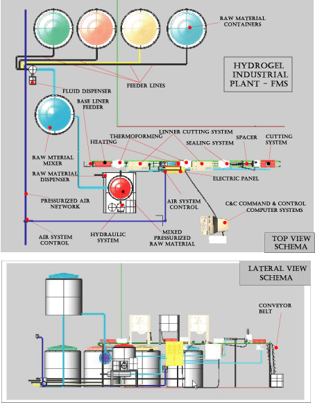
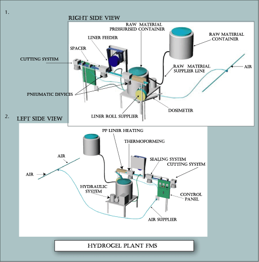
SCHEMATIC
HYDROGEL
FLEXIBLE MANUFACTURIGN SYSTEM |
 |
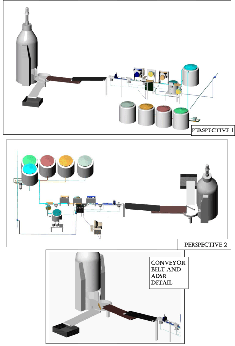
__________________
PERSPECTIVE
|
 |
__________________________
GENERIC
FMS
STERELISATION AND ADSR MODULES
The
generic model is applicable to a vast chemical
and cosmetics products lines using
sterilisation by irradiation and ADSR – Automatic
Distribution Storage Retrieval Systems.
|
 |
|
|